
Inside an Area Gamma Monitor: From Detector to Alarm Output
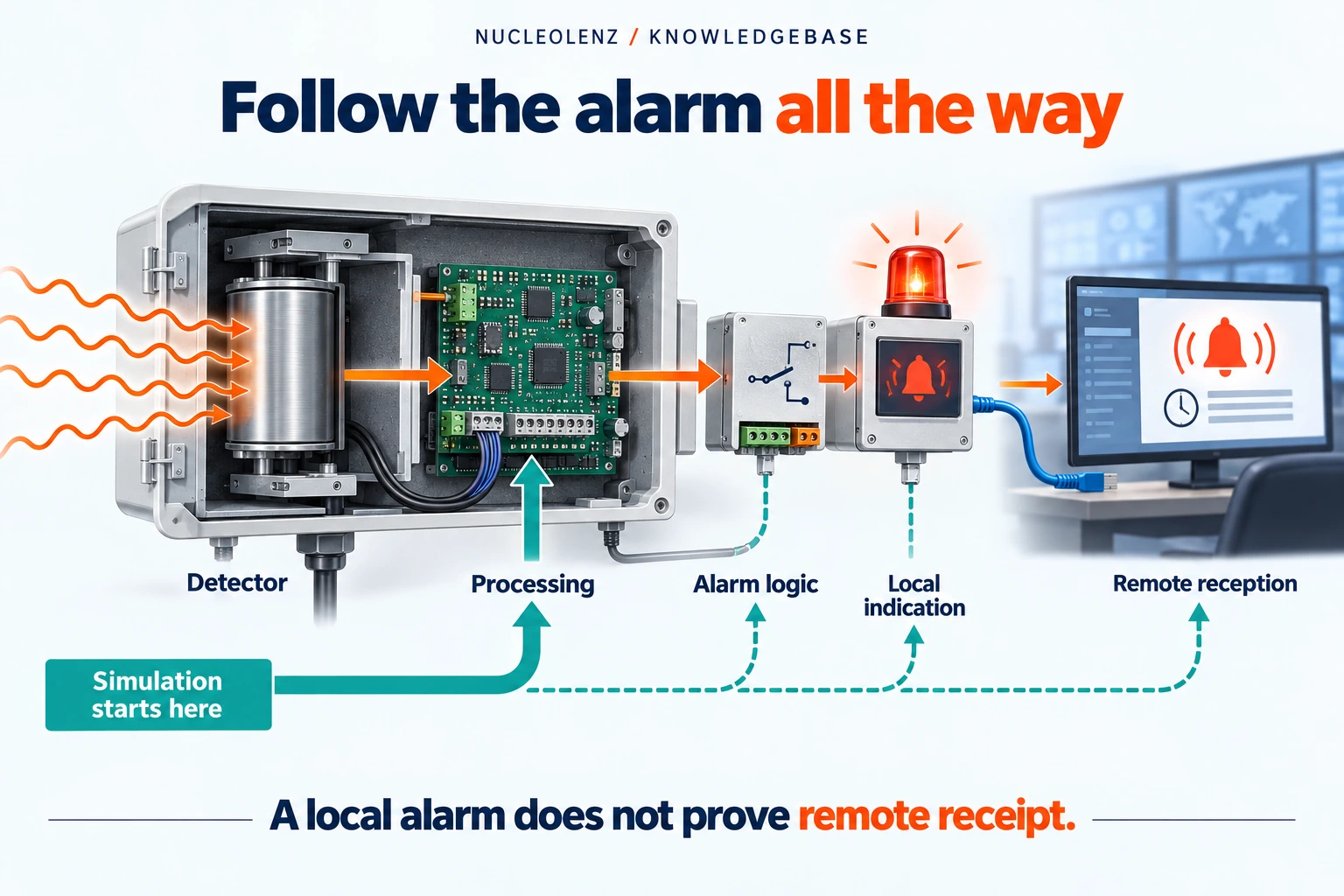
Follow a fixed gamma monitor from detector response to displayed value, alarm and remote output. Understand why each part of the chain needs its own verification.
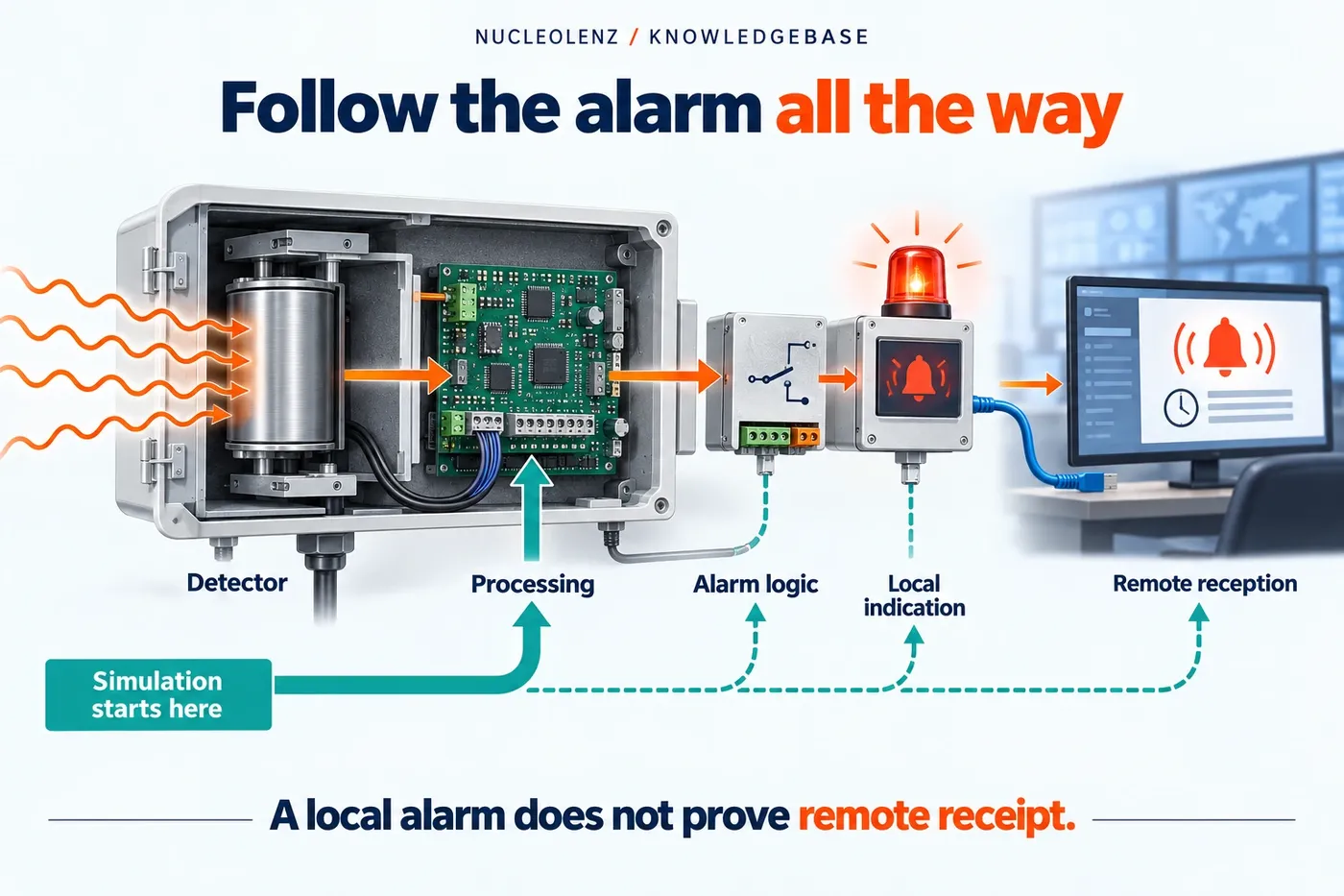
Open the concept graphic at full size ↗
Three key ideas
Detect, interpret, communicate
- Detect: A suitable detector converts radiation interactions to signals.
- Interpret: Configured processing produces the stated measurement.
- Communicate: Displays, alarms and outputs convey defined information.
At a glance
Compare the key distinctions
| Function to verify | Evidence needed | Insufficient on its own |
|---|---|---|
| Detector and measurement | Response under defined radiation conditions | A communications test alone |
| Local alarm | Configured indication or alarm behaviour | A detector calibration alone |
| Remote output | Correct reception and interpretation | A local sounder test alone |
| Status information | Meaning of fault or unavailable states | A normal-looking value without status |
The diagram is conceptual. Confirm detector, interfaces, status handling and tests against supplied documentation.
A fixed gamma monitor connects a radiation-sensitive element with information that people or other systems can use. Understanding that chain helps explain why an alarm test, a calibration and a communication check are different activities.
The detector starts the chain
Radiation interactions in a suitable detector produce signals that the electronics can process. Different monitor configurations can use different detector technologies. The choice affects response characteristics and must fit the intended measurement.
This is a functional explanation, not a circuit diagram of a particular Nucleolenz model. The supplied hardware documentation is needed to establish the exact detector, operating conditions and service arrangements.
Processing turns signals into an indication
The system processes detector information using its configured measurement method. A display can present the relevant quantity, while status information can identify operating or fault conditions. The result depends on the complete calibrated configuration, not just the detector element.
Outputs connect the measurement to the workplace
Nucleolenz's Indoor Area Gamma Monitor is listed with relay, 4–20 mA, RS-485 and Ethernet interfaces. Where those options are supplied and used, commissioning should establish how the receiving system interprets them.
A visible local alarm does not prove that a remote message or connected response was received. Likewise, an electrically simulated output does not establish the radiation response of the detector. Test evidence should name the part of the chain actually exercised.
Trace an alarm from the receiving end
Imagine a commissioning exercise in which the local display shows an alarm but the control-room display remains normal. The useful question is where the two paths diverge. Is the configured output intended to represent that alarm? Is the receiving channel interpreting the correct signal and units? Does the record show a fresh value or an old one? These are commissioning questions for the supplied system documentation.
An operator should not resolve the discrepancy by assuming that one display overrides the other. Preserve the observed states and refer to the approved test procedure. A clear diagram of the installed signal path makes it easier for the responsible team to identify which part has actually been demonstrated.
Distinguish three kinds of evidence
- Radiation response: evidence about how the complete measurement configuration responds under defined irradiation conditions.
- Alarm function: evidence that the configured alarm logic and intended local indications behave as specified in the test.
- Transmission and reception: evidence that the connected output reaches the receiving system and is interpreted correctly.
These tests can overlap, but their scope must be explicit. A simulated electrical input may exercise downstream processing without testing the detector. A local sounder test can demonstrate audibility at an observation point without demonstrating a remote relay or network event.
Include unavailable data in the explanation
A monitoring display needs context when data are absent, stale or outside the valid operating state. The actual fault indications and their transmission depend on the supplied configuration. Ask how operators distinguish an ordinary low reading from a failed or unavailable measurement, and record the answer in the commissioning documentation.
For later changes, retain the detector configuration, software or firmware identification where applicable, settings and receiving-system mapping. An interface modification can alter the meaning presented remotely even when the local meter is unchanged. The takeaway is to verify the entire installed information path while stating precisely which test supports each claim.
Record the model and configuration alongside the alarm settings and receiving-system arrangement. Operators need to know what the monitor reports, what a fault looks like and which site procedure applies. That knowledge makes the monitor's output easier to interpret without assigning unsupported capabilities to the device.
Check your understanding
Put the idea to work
Choose an answer, then reveal the explanation. Your answers stay in this browser.